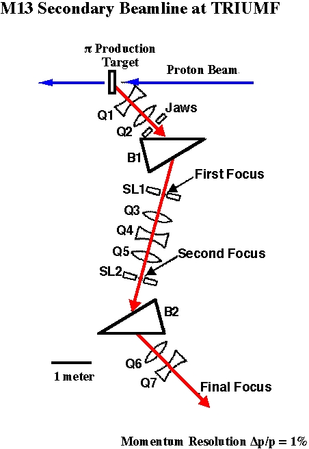
Here's a schematic of the parts that make up M13 and where they are relative to each other. I don't think this is to scale, but it shows the sequence. What we call F0 (focus zero) is at the point marked "Jaws", where we have a horizontal slit and a vertical jaw to limit the acceptance (or divergence) of the beam. The points marked "First focus" and "Second focus" we also call F1 and F2 respectively. In the original M13 design, these were symmetric momentum-dispersed focuses. At the moment, we have a horizontal slit in each position. Usually we control the momentum acceptance with the slit at F1, and set the slit at F2 to clean up any particles scattered from the slit at F1. This means that the F2 slit should be set a little wider than the F1 slit for production running. Jaap Doornbos estimates 1.25 cm at F1 gives 1% momentum bite.
The M13 Absorber Wheel is located at F1 ("First Focus").
There is now a vertical slit at F2 ("Second Focus"), although we do not have EPICS control to it.