From: Robert Henderson <rhend@triumf.ca>
Date: Tue, 13 Jun 2000 17:16:10 -0600
To: E614Mechanical@relay.phys.ualberta.ca
Subject: Status of Cradle/track concept
To: E614 Collaboration
Frome: Robert Henderson (TRIUMF)
Re: Status of cradle/rail design
Date: 13 June 00
This is to bring people up to date about progress with the cradle/rail
concept. Hans leaves at the end of June. We plan to have the concept
finished
by then, ready for someone to detail. There will be a TRIUMF engineering
review of the cradle/rail concept around the end of the month. The
drawings
shown are NOT final, we are fiddling several things such as the exact
shape
of the plug etc.
I have managed to to produce .JPG drawings which are far smaller than
the
.EPS files I posted last time. They are:
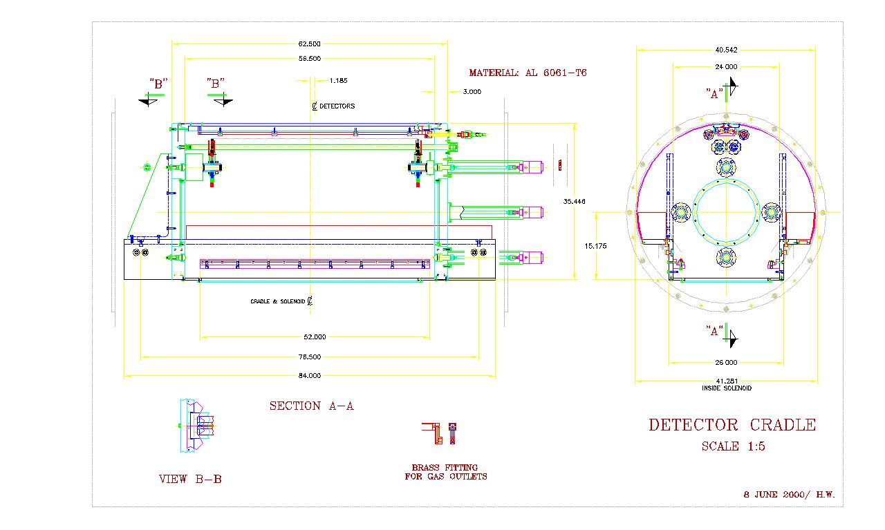
CRADLE.JPG - side and end view of cradle (left is upstream).
RAIL.JPG - side and end view of rails (left is upstream).
BOTH.JPG - side and end view of cradl/rails (left is upstream)
Most of dimensions are stripped off to simplify view.
PLUG.JPG - Views of possible plug layouts
TENSION.JPG - Closeup of tension rod at DS endcap
Features:
--------
1) It is obvious the horizontal part of the cradle beams could extend
out to
R=515 mm and meet the `shell'.
Hans has found we can get the aluminium thick enough to do this. The
raw
beams will cost about C$3k each and there will be more material to
machine
off, but we both believe these costs will be offset by not having to
make the
`lip extensions' and tap a lot of holes in the beam lip etc.
So, unless people can think of a good reason we'll go with the solid
longer-lipped beam. In the endview of CRADLE.JPG and BOTH.JPG a solid
beam is
shown on the left side and and a beam with extension on the right side.
light-weight 2.75" wide bolt-on extension to the lips.
2) An obvious feature of the cradle design is the pneumatic cylinders
attached to the DS side of the DS endcap.
These cylinders are meant to anable us to remotely apply or adjust the
axial forces at the four cital columns. With a diameter of 2.5" and an
air
pressure of 90 psi each cylinder can apply up to 200 Kg. In addition,
each
cital will has a spring that applies 20 Kg. These springs will apply a
modest
axial force even if the cylinder pressure is missing or lost.
The cylindes are double-acting, that is they can pull as well as push.
Thus, we can use the cylinders to pull back the bumpers against their
springs
during module removal/installation. Going to double-acting cylinders
will
change the cylinder/bumper coupling from that shown in CRADLE.JPG, i.e.
it
can't just `cup over' the bumper end as shown. Hans is working on it.
The most obvious feature of the cylinders is that they are attached to
the
endcap with long pipes!? Why?
The reason is that the cylinders are made from 304 stainless. Though
nominally non-magnetic, I decided that they should be as far from the
central
region as possible. Thus the mounting tubes are about 13 inches longer
than
usual and the cylinders are moved DS almost to the steel yoke. I agree
it
looks `weird', but the reasoning is sound. Also, it's not `cast in
stone', if
down the road we find they are a hinderance, we could have shorter
mounts and
coupling rodes made, the replacement would be easy. There will be vent
holes
to these pip volumes to make sure they don't act as long-term air leaks.
The springs are at present in the DS endcap, but since they are steel,
I'm
going to see if Hans can move them to near the cylinders.
3) The area of the plug through the DS endcap is being worked on. Hans
and I
should converge quickly.
4) The concept for the tension rods is finalised (see TENSION.JPG).
This relies on a turned washer (brass or Aluminium). This `washer'
(shown
hatched on the figure) has two surfaces, one engages on a shoulder on
the
tension rod, the other on the endcap surface. The distance between these
two
surfaces will be made shorter than expected, then the surface mating to
the
tension rod will be smimmed to the correct vlaue determined during
assembly.
This washer prevents over-tightening the tension rod.
5) Hans and I are working on the region at the top of the cradle.
This is where the gas outlet manifolds and tension rods are. The
maniolds
have to be supported and alighned etc. We are designing a `bridge' that
connects (loosely) to the two endcaps.
If we have a single piece `shell' it will simply enclose this
`bridge'.
But we both think a single piece shell would be very clumsy. So we are
looking ito having two `half-sells' that also seal on the outside
surface of
the bridge. This is not quite ready to present yet, soon though.
 Filename: both.jpg
 Filename: cradle.jpg
 Filename: plug.jpg
 Filename: rail.jpg
 Filename: tension.jpg
Status of Cradle/track concept / Robert Henderson
- Created for the The Center for Subatomic Research E614 Project Projects Page.
- Created by The CoCoBoard.
 Filename: cradle.jpg
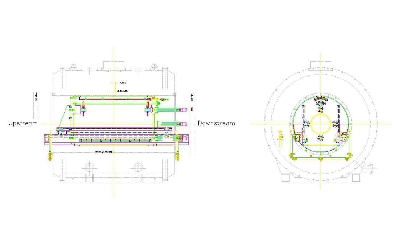 Filename: both.jpg
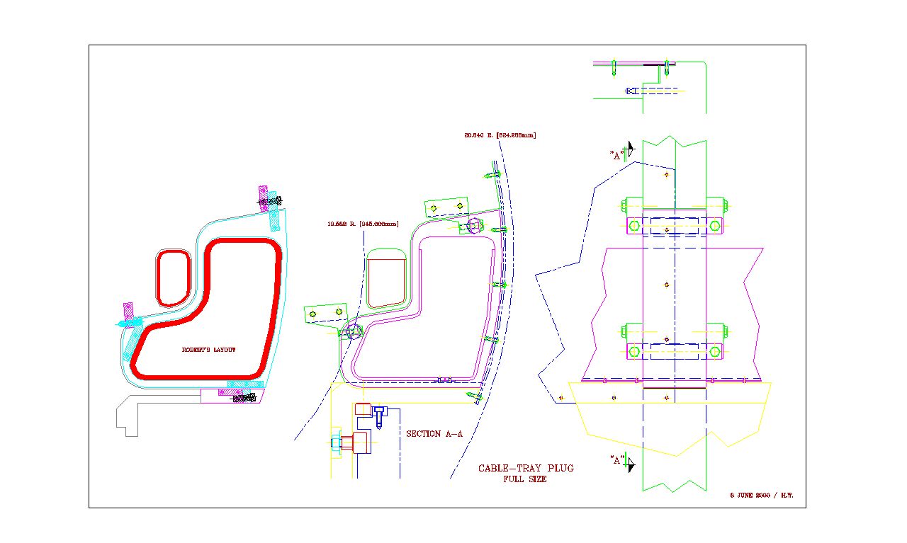 Filename: plug.jpg
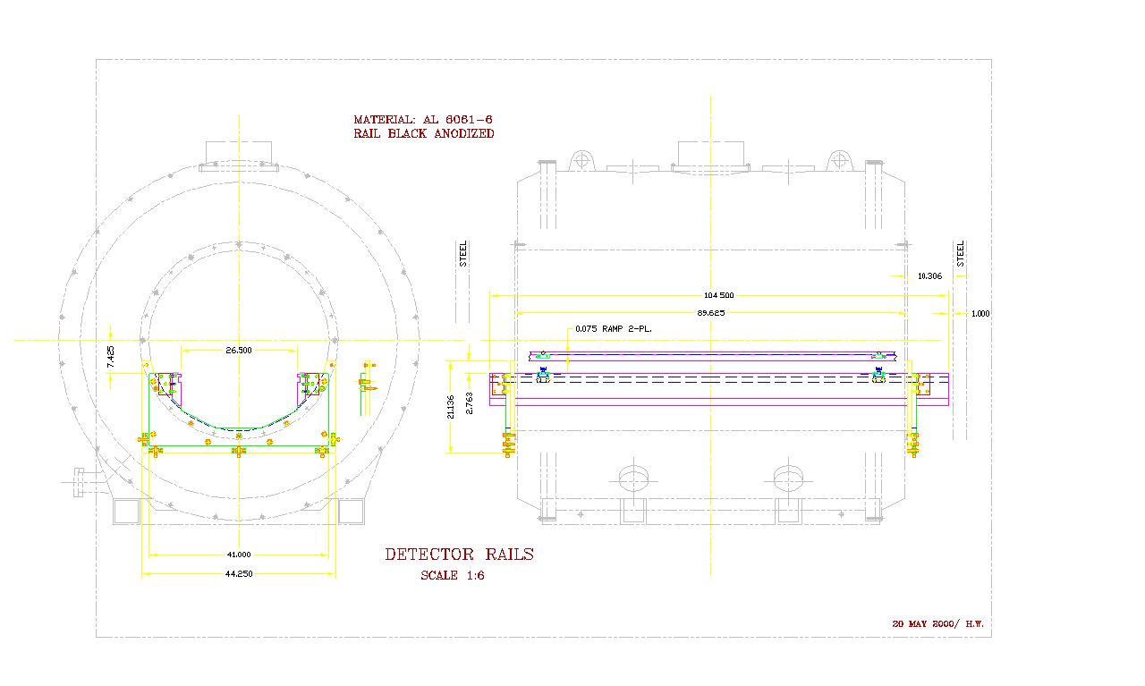 Filename: rail.jpg
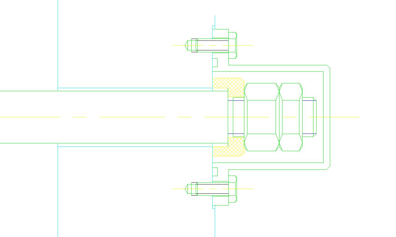 Filename: tension.jpg