From: Nathan Rodning <nathan.rodning@ualberta.ca>
Date: Thu, 19 Apr 2001 22:02:52 -0600
To: e614electronics@relay.phys.ualberta.ca
Subject: [Fwd: Problems with analogue cables]
--

Nathan Rodning, Associate Chair
Professor of Physics
University of Alberta
Edmonton, Alberta   T6G 2J1
Canada
(780) 492-3518  /  Fax:  (780) 492-0714
http://www.thehungersite.com/
An embedded message follows:
From: Brian Evans <tronics@triumf.ca>
Date: Thu, 19 Apr 2001 17:25:19 -0700
To: Doug Maas <maas@triumf.ca>, Grant Sheffer <sheffer@triumf.ca>, Robert Henderson <rhend@triumf.ca>, Nathan Rodning <rodning@relay.phys.ualberta.ca>, Ethan Lai <ethanlai@triumf.ca>
Subject: Problems with analogue cables
Folks:
This is to bring to your attention a problem with the analogue cables
for TWIST.
Recently there has been a much higher return rate of failed cables to
the shop. One recent box of 8 had 6 failures (75%). We had been running
at one failed cable out of about 40 -50 (2-3%).
I'm afraid to say, but I think the cables are failing due to an overly
aggressive mechanical test component or over-handling of the cables
during testing.
I have attached a number of pictures that outline some of the problems.
#74
Shows 2 wires broken off about 1/2 inch down the cable
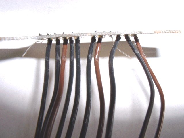
#75
Different view that shows the 2 broken wires plus a large amount of
insulation damage
#78
This board has had 2 wire broken off right at the solder fillet junction
#84
Close-up of the damage to the insulation. It appears to have been sawed
back and forth along the edge of the board.
#86
Shows the damage at the end of one of the wires that has broken of about
a 1/2 inch down the cable.
I eliminated our stripping machine as a problem as I thought that the
grippers might be crimping the cable causing some stress on the inner
conductor. I stripped a number of ends then peeled the ends by hand in
the area that the stripper gripped (and where the problem appears). I
then examined the ends under a microscope looking for any marking of
which there were none. Further, the problems are only occurring at the
16 or 24 way paddle boards and not at the 8 way ends that go into the
Post-amps. If the problem was related to the shop, I would expect to see
it at both ends.
I tried to recreate the damage to the end as in picture #86. First I
bent the cable back and forth till it broke, this takes between 20 and
24 times ( 5 tests) I examined the ends but they had a different pattern
to #86. I then pulled lengthwise on the cable but this resulted in a
tapered deformation on the ends. I then bent the cable while maintaining
a modest load on the wire. This produced a very similar result to
picture #86.
I also examined some freshly made up cables and they exhibit no abrasion
of the insulation as in the defective cables. They also have no
indication of any bending at the points that are causing problems.
The abrasions are being cased by contact with the PC board. My guess is
that the boards are being handled in such a way that the insulation is
rubbed against the board numerous times. The broken wires in most cases
are at the point of the abrasion or slightly above it.
Another problem is that a large number of strands of the shielding
braids on some of the boards have been broken off. It took only one or
two flexes of the cables to break the shield off completely. Again,
examination of boards just leaving the shop show that of the 40 or so
fine strands, only a maximum of 4 or 5 are broken off with the average
probably 1 or 2.
I am concerned that some of the cables may be compromised in that they
may have been flexed to the point where they are about to fail. In
examining some of the defective cables, it took very little effort to
break some of the adjacent wires. Some wires also have the appearance
and feel of a weak portion in the problem area. If wires in this shape
have been potted up, they may fail from installation handling or thermal
cycles in the future.
I'm afraid that I have no suggestions on methods to test for defective
cables once they are potted up. You may just have to install the cables
and hope we have enough spares for future failures.
In regards to repairing these cables, I need to be able to shorten the
cables by a minimum of 3/4 of an inch with 1 inch being a better length
to get past any stressed cable and 1 -1/2 being an optimum. I had also
asked many months back for single coax cable to be ordered from the same
lots so that we could lay in a single wire if needed. This item seems to
have been forgotten. Cables with a single repaired wire could have been
left for use in the lab. This is probably impossible now if we have a
conflict with Bay over the 2000 extra feet.
All this highlights my requests from earlier in the project. These
cables are delicate and must be handled with care. With a number of
potential failures possible, we now need to handle the cables much more
carefully at all stages. This includes any more testing, lab work,
installation and especially during R+R work in the chamber over the next
few years.
Clearly concerned parties need to get together to discuss this issue. I
also need a decision on cutting the cables back. Can it be done ? if so,
how far back can they be cut. Will we need to keep track of any shorter
cables ? We will if they are repaired more than once.
If we ever do this again, we need to stick to one to one paddle boards
with built in strain relief such as the one we are using at the post-amp
end.
Brian
 Filename: Dscf0074.jpg
 Filename: Dscf0075.jpg
 Filename: Dscf0078.jpg
 Filename: Dscf0084.jpg
 Filename: Dscf0086.jpg
[Fwd: Problems with analogue cables] / Nathan Rodning
- Created for the The Center for Subatomic Research E614 Project Projects Page.
- Created by The CoCoBoard.
 Filename: Dscf0075.jpg
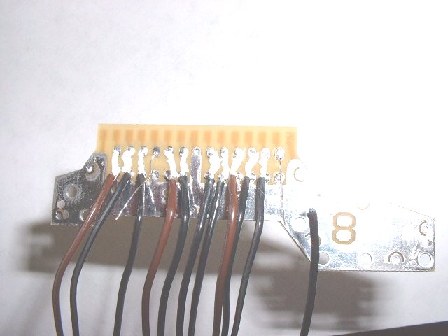 Filename: Dscf0074.jpg
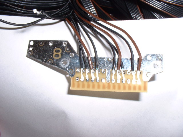 Filename: Dscf0078.jpg
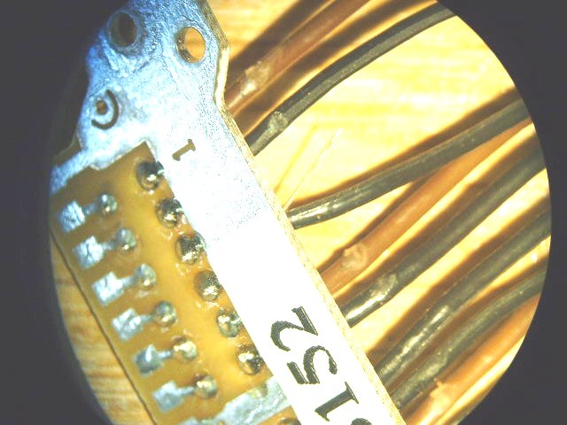 Filename: Dscf0084.jpg
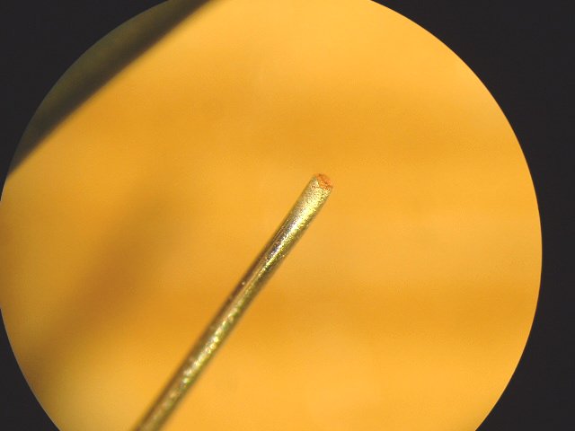 Filename: Dscf0086.jpg