From: "Grant F. Sheffer" <sheffer@erich.triumf.ca>
Date: Tue, 21 Dec 1999 15:45:21 -0800
To: e614chambers@relay.phys.ualberta.ca, rodning@relay.phys.ualberta.ca
Subject: Latest Cross-talk results with Modified Lamel
See attached files
Cross-talk Results - 21 Dec 1999
To: E614 Collaboration
From: Robert Henderson
Date: 21 Dec 1999
Re: Cross-talk results
Cross-talk results
The detector plane with no `grounds' (HV grounds) has been butchered
as shown in the December 10/11 collaboration meeting. A section of the lamel
was cutout and replaced with a good approximation of the new lamel fan-out.
See lam-50-6.eps
One of the 24 channel preamps was also modified to approximate a new preamp
setup. The new preamp design would have 2 mm pitch input connectors instead
of 2.54 mm (0.1"), but with alternating signal/HV-ground. The existing preamp
was modifed to have alternating signal/HV-ground, so only 12-channels are
readout. These 12 channels cover the center two 6-channel dies, the other
dies have their inputs grounded.
The 12 channels of readout are referred to as S#1 to S#12. With regard to
dies, analogue output cable and ribbon cables the situation is as follows:
Die Die
--------------------- ------------------------
S# 1 2 3 4 5 6 7 8 9 10 11 12
------------ ------------------------------ --------------
A-cable/ B2-1 8 1 b2-2 8 1 b2-3
ribbon
These modifications have now been tested with the PPP using Ar/Iso (25/75)
and an Fe55 source. The modified region is read out with the origional
preamp, i.e. NOT the staggered intput connector. The results are discussed
below.
In addition, I have done a comparison of the preamp output with the 1kohm
pull-down resistor (PD) and without the pull-resistor (NPD). Removal of this
resistor does NOT change the gain of the preamp.
Results
The cross-talk is GREATLY reduced!!!
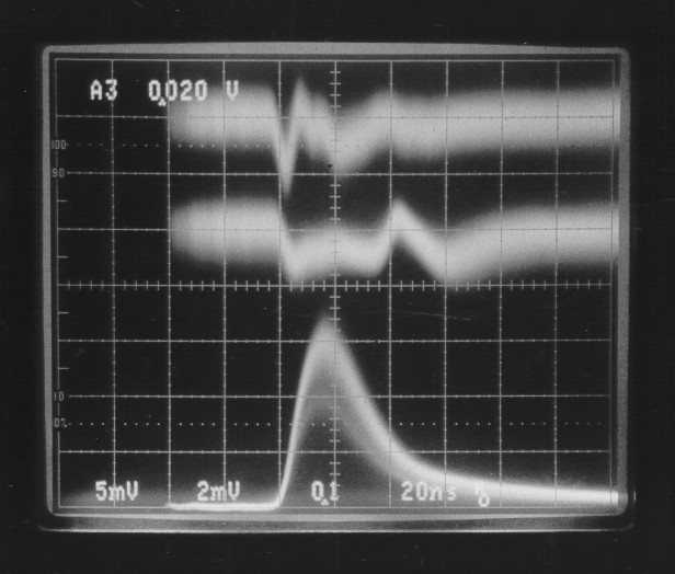
(1) Photo ct01.jpg shows the situation with the scope triggered on S#4 (300 mV
pulses) and viewing the adjacent channels with (PD) and without (NPD)
pulldown resistors.
*** The PD cross-talk is now 0.5% instead of nearly 3%
*** The NPD cross-talk is even lower, it's 0.2%, a factor of 2.5 better.
Other channels were checked, these values are typical, except for the
first/last channels of the die. In addition the positive part of the Ct for
the NPD case is NOT prompt, it's delayed by about 30 ns.
The cross-talk pulses look somewhat different. In addition, the white-nosie
level is a factor of 2 better without the pull-down resistor (NPD).
*** The PD white-noise is approximately 1.6 mV p-p.
*** The NPD white-noise is approximately 0.8 mV p-p.
(2) Photo ct02.jpg shows the scope triggered on S#3. S#6 (last on die) is
shown for both tha PD and NPD case (double exposure). The scope scales
are 5 mV/cm and 2.5 mV/cm respectively.
*** The PD cross-talk is 1.5%, unchanged from past results.
*** The NPD cross-tal is 0.8%, almost a factor of two better than PD.
(3) I then increased the voltage to produce saturated pulses on the VTX. I
esitmate they were at least 700 mV pulses. Photo ct03.jpg has S#4 as
trigger and shows the adjacent channels (both on 5 mV/cm).
The PD cross-talk shape is somewhat worse to that for un-saturated pulses,
approximately 0.7%. But this is uncertain since the S#4 pulses are assumed at
700 mV, they might be 1000 mV, which would again give 0.5%
The NPD case is 0.2% assuming 700 mV pulses, a factor of 3.3 better than
the PD case. Again, the NPD positive cross-talk part is delayed, but now by
about 40 nsec.
(4) Photo ct04.jpg shows the same channel readout
with PD and NPD to compare
pulses. The voltage is lower again, the pulses unstaurated. The gain
and pulse shape appears very similar.
The above results indicate a large reduction in cross-talk with the new
fan-out scheme. Eliminating the pull-down resistor produces further
improvements in noise and cross-talk. The worst cross-talk now comes from the
first/last channels of the VTX die. This CT of 1.5% for PD and 0.5% for NPD
is VERY annoying, since it occurs on first/last when ANY of the die channels
has a pulse!
(5) I spent some time `playing', trying to find something (anything!) that
would effect this problem. I finally tried removing the capacitor between
channels S#6 and S#7. Photo ct05.jpg shows the scope triggered on S#3 and
looks at S#6 with and without pull-down resistor (double exposure).
*** The PD cross-talk is reduced from 1.5% to 0.8%, almost a factor of two.
*** The NPD cross-talk is reduced from 0.8% to 0.43%, almost a factor of two.
This reduction in cross-talk is again large! These capacitors between dies
appear to be filter caps on the +4V line. It is quite common to do this. I'm
unsure why they are causing this cross-talk, it is probably a layout problem.
I've asked wayne to find out why they were added, just on principle or to
solve a problem. We CAN remove these caps from our VTX board quite easily and
perhaps substitute at a different location. Although I removed the cap
between S#6 and S#7, the pad for it are still there and may be contributing
to the remainder of the CT I see on S#6.
Conclusions
This exercise has been VERY rewarding! The new lamel layout seems well
supported. Eliminating the pull-down resistors and the capacitors between
dies leaves is with cross-talk of about 0.43%, worst case. This represents a
huge improvement over the 2.9% values we had previously.
 Filename: lam-50-6.eps
 Filename: ct01.jpg
 Filename: ct02.jpg
 Filename: ct03.jpg
 Filename: ct04.jpg
 Filename: ct05.jpg
~~~~~~~~~~~~~~~~~~~~~~~~~~~~~~~~~~~~~~~
Grant F. Sheffer (sheffer@triumf.ca)
TRIUMF - Scientific Instruments Manager
Tel (604) 222-1047 ext. 6575
Fax (604) 222-1074
Latest Cross-talk results with Modified Lamel / "Grant F. Sheffer"
- Created for the The Center for Subatomic Research E614 Project Projects Page.
- Created by The CoCoBoard.
 Filename: ct01.jpg
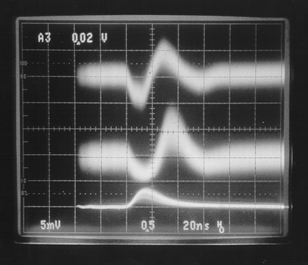 Filename: ct02.jpg
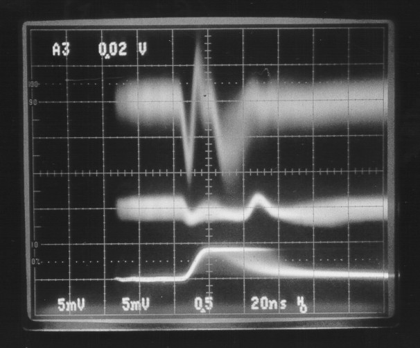 Filename: ct03.jpg
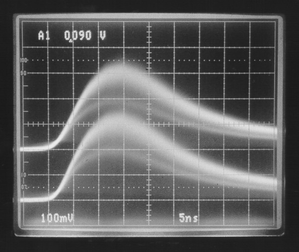 Filename: ct04.jpg
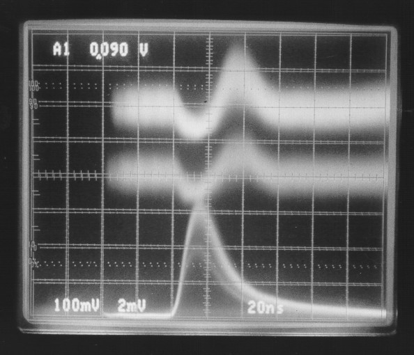 Filename: ct05.jpg