
This report covers the work done to investigate sources of crosstalk in the E614 preamplifier board prototype. This is the preamp board used in the August beam tests. The preamp board consists of the VTX circuit board mounted on a motherboard ( the preamp board ). The preamp board contains input connectors to the chamber and output connectors to the post amp via coaxial cabling. Also on the preamp board are high voltage coupling capacitors between the input connectors and the VTX plus a high voltage distribution bus utilizing high ohmic resistors for isolation, plus a protection circuit for the input of the VTX utilizing N channel Jfets. The approach taken to test for crosstalk was to take a bare preamp board and add each component to the board and to look for crosstalk as each component was added. This was done working from the output of the board to the input of the board. The circuit used for pulsing the input was: VTX-TST.PS
The top trace is channel 9 of the preamp at 100 mV/div
which is the channel with the input pulse applied.
The middle trace is ch# 10 at 2 mV/div an adjacent channel.
The bottom trace is ch# 9 at 2 mV/div an adjacent channel.
The crosstalk is about 1.0 % for adjacent channels.
As components were added to the preamp board very little apparent crosstalk was noted until the input connector was added to the board. It appears that this input connector is the greatest contributor to crosstalk on the board. The traces as shown above only appeared after the insertion of this connector. This input connector is a SAMTEC single row horizontal entry box connector strip. This is a connector with sockets on a spacing of 0.100" between contacts. The sockets are designed to mate with a 0.025" square post.The contacts have two beam contacts which are spread as the .025" post is inserted. These beams, as they spread, move closer to the beam in the adjacent contact, and when pins were inserted into the contacts the crosstalk as shown above increased by about 10%. To try and decrease the crosstalk on the preamp board the original input connector was replaced by a double row version of the horizontal entry box connector. Every second contact was removed so that the contacts were staggered row to row. This cut the crosstalk on the preamp by about 50% as shown in the following:

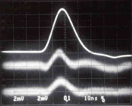
Top trace ch# 9 100 mV/div
Middle trace ch#10 2 mV/div
Bottom trace ch# 8 2 mV/div
The crosstalk is of the order of 0.50 % for adjacent channels. 0.50 % is the quoted spec for the crosstalk of the VTX circuit board.
During the testing the following was observed:

Top trace ch# 9 100 mV/div
Middle trace ch# 11 2 mV/div
Bottom trace ch# 12 2 mV/div A channel on a
die end of the VTX
These signals never appeared on the adjacent channels. The signals would get progressively smaller as you moved to channels farther from the channel with the applied input signal. The exception to this was that the signal would get much worse at channels which corresponded to the amplifier channels at the ends of the dies on the VTX board. This is shown in the bottom trace of ch#12 above. These signals did not change with the addition of components on the preamp board. They seem to originate on the VTX board and are therefore beyond our control.
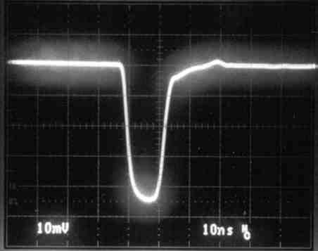
You will notice on the top trace ( ch# 9 ) above that there is a small negative going component to the output signal. This appeared after the addition of the 100 pF HV coupling capacitor. If the value of the coupling cap was increased to 180 pF this negative going component was much smaller and also the amplitude of the positive pulse increased by about 10%. This indicates that the value of the HV coupling cap may have to be increased.


Top Trace ch# 3 100 mV/div
Top Trace ch# 3 100 mV/div
Middle Trace ch# 4 2 mV/div
Middle Trace ch# 4 2 mV/div
Bottom Trace ch# 6 2 mV/div
Bottom Trace ch# 6 2 mV/div
The above two scans were done during early testing when only
the VTX board was mounted on the preamp board.
One thing interesting to note is the difference in the pulses
when the 1K ohm pulldown resistor is left off the output of the
preamp.
The scan above left is of an adjacent channel and a channel 2
away from the channel with the applied input. In this trace the
1K ohm pulldown is in the circuit.
The scan above right is the same except that the pulldown resistor
is missing from the circuit.
All further tests were done with the 1K ohm resistor in the circuit.
The 1K ohm pulldown resistor is mainly there to allow some dynamic
range for negative going pulses. We may have the option to leave
this resistor out of the circuit.
 Filename: Final.jpg
 Filename: Input.jpg
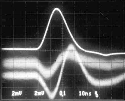 Filename: L-a-de.jpg
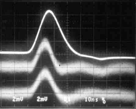 Filename: Orig.jpg
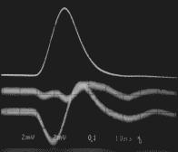 Filename: Out2a.jpg
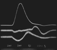 Filename: Out2b.jpg