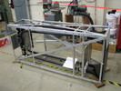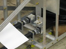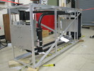
01 Frontview lookingDS [576k]
Pic 1: Front view (looking DS) - The frame extends 1/2" giving partial protection if we push the scintillator too close to the yoke hole. - There are 2 large braces on the top of the frame. Initially is was going to be one on the top and one on the bottom, but then the frame would not sit level on a table.

02 Sideview showingbracing [575k]
Pic 2: Side view (showing bracing) - Rather than many small braces, it was only necessary to use long braces on the side. - The frame is very strong and resistant to twisting with this level of bracing.

03 Topview lookingUS [525k]
Pic 3: Top View (looking US) - Again, the two braces on top are visible. - The two upper light guides have been angled to allow for easy insertion/removal of PMT tubes/bases from shields.

04 Light guide to pipe joint unwrapped [434k]
Pic 4: Light guide joint (unwrapped) - This is a fairly major change - to really support the join between light guides and the long light pipe, Steve and Jesse machined extra plates and holders to hopefully prevent breakage.

05 PMTHousingplate [501k]
Pic 5: PMT housing plate - This extra plate was not in the design plans. The end result is that PMT shields are well spaced - the original design would have been very tight.

06 Framebackplate [501k]
Pic 6: Frame back plate - The original design called for a much larger back plate. The frame and this smaller back plate are more that sufficient in strength and rigidity.

07 Sideview lookingUS [539k]
Pic 7: Side view (looking US) - The original design had the light pipes being supported on the other internal frame piece - this wasn't necessary due to the extra clamping at the PMT's and the glue joing. - Note that the bend is as gradual as possible in the large light guides.