Basic Beamline Instructions - TWIST 2001
Controlling M13 with TICS
This page is designed to show you make basic modifications to the M13
beamline (changing momentum, manipulating slits, etc). For (lots)
more information, see the TICS documentation (it's in a binder on the
shelf in the counting room).
Basic TICS operation
The TICS interface is in the "Executive Class" part of the counting
room. It's the grey monitor with the funky magnet-induced colours all
over it, in the back corner by the whiteboard.
You control TICS using the numeric keypad. On the bottom right corner
of the screen is a grid which tells you how the keys are mapped (ie.
what will happen if you push one). This mapping is almost
never the same as what's on the keys. In particular,
2 (down arrow) does not move the selection down. It
usually modifies the setting of whatever beamline element you've got
selected. 5 acts as the down arrow. Use caution!
TICS is composed of several pages of information,
such as magnet settings and slit settings (which are probably the only
two pages you'll ever need). You can flip between
pages with the "Next Page" key (9, I think; check the
screen).
On each page are various elements you can select (eg.
magnets, or slits). Move between elements with what
TICS uses for "arrow keys". Change them with the buttons TICS shows
you.
[Top]
Adjusting Slits and Jaws
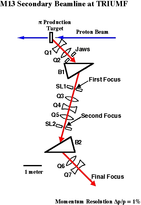
See the M13 schematic below for where all the slits
and jaws are. You can set them on the slits and jaws page of TICS.
HSL elements are Horizontal Slits, and the VJ element is the vertical
jaws. (The difference is that each side of a slit can be controlled
independently, allowing both position and width control.)
Set the width and/or position using the "Set" key
(3). You'll probably only be able to get it within half a millimetre
or so. The readings seem to jump around a lot. If you're out by more
than that, enter the "Set" command again and see if that helps. If it
doesn't, try overshooting by a few percent then backing up. Also,
double check the position after adjusting the width (or vice versa)
for a slit; changing one can change the other.
Beamline Schematic
Here's a schematic of the parts that make up M13 and where they are
relative to each other. I don't think this is to scale, but it shows
the sequence. F0HSL (F0 horizontal slit) and F0VJ (F0 vertical jaws)
are located at the point marked "Jaws". F1HSL and F2HSL are located
at SL1 and SL2, and are used to select the momentum (and the momentum
bite; Jaap Doornbos estimates 1.25 cm at F1HSL gives 1% momentum bite).

back to the Operating Instructions page
back to the main Run page
