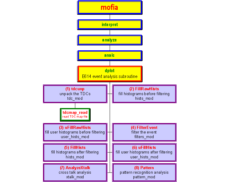
Figure 6. MOFIA 2.0 analysis branch.
 MOFIA
2.0
A schematic view of the MOFIA 2.0 analysis branch is shown
in Figure 6. The procedure dplot
is the E614 event analysis subroutine. From dplot
calls are made to analyze the event starting with the TDC unpacking, filling
the histograms, filtering the event, etc.
III..1 TDC Unpacking
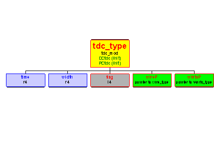
From dplot a call is made to the PUBLIC function tdcunp in module tdc_mod, in order to unpack the TDCs. This module also contains the declarations and initializations (and filling) of the data structures associated with the TDC hit structures which are shown in Figure 7. Table 3 shows a brief description of the tdc_type structure. This type has two instantiations, DCtdc(ihit) and PCtdc(ihit). The first two components of the structure are the time and width of the TDC signal. The third component, flag, is an integer that is assigned a zero value for normal TDC signals, and a non-zero value if the TDC signal has a peculiar characteristic (such as a leading edge but no trailing edge, etc). Table 4 contains a listing of these flags. The last two components in this structure are two pointers. The first, wireP, points back to the wire geometry structure and, therefore, provides the link between the hit structure and the geometry structures. To point to the wire and plane numbers for a particular DC TDC hit, for example, we have

Figure 6. MOFIA 2.0 analysis branch.
INTEGER (i4), POINTER :: iwP, ipP
iwP => DCtdc(ihit)%wireP%iwire
ipP => DCtdc(ihit)%wireP%planeP%iplane
and so on. In the above example we could have defined integer variables iw and ip (instead of pointers iwP and ipP); in which case we have
INTEGER (i4) :: iw , ip
iw = DCtdc(ihit)%wireP%iwire
ip = DCtdc(ihit)%wireP%planeP%iplane
However, since copying data from a structure to a new variable is generally less efficient than using a pointer, it is recommended that the above style be used.

|
|
Description |
|
Details |
|
|
Good hit | Trailing edge followed by leading edge on same channel | |
|
|
No leading edge |
|
Trailing edge following another trailing edge |
|
|
No leading edge |
|
Last edge on channel, but itís a trailing edge |
|
|
No leading edge |
|
Last edge was a trailing edge from a different channel |
|
|
No trailing edge |
|
First edge on channel, but itís a leading edge |
|
|
No trailing edge |
|
Leading edge following another leading edge |
|
|
No leading edge |
|
Last edge on channel is a trailing edge |
|
|
No trailing edge |
|
First edge on channel is a leading edge |
|
|
Width < 0 |
|
Trailing edge followed by leading edge, but width < 0 |
DCwhits(26,32)%nhits
To assign two pointers, ihitP and timeP, to the hit index and TDC time for the second hit on this wire we have
INTEGER (i4), POINTER:: ihitP
REAL (r4):: timeP
ihitP => DCwhits(26,32)%hits(2)
timeP =>
DCtdc(ihitP)%time
The above example demonstrates another case of assigning pointers to a component of a structure. While the last two lines may have been combined in one, so thatFigure 8. MOFIA 2.0 wire hits structure.
timeP => DCtdc(DCwhits(26,32)%hits(2))%time
the style of assigning a pointer makes the code more readable. It is also more efficient, since typically such statements would be inside do loops (looping over planes, wires, hits, etc), and hence the hit number is extracted from the structures once by assigning it to a pointer(ihitP, in this case), and the pointer is then used within that loop from that point on. Another useful technique is to assign a pointer to a structure (as opposed to a component of a structure in the examples above). This also provides faster execution time; and improves the readability of the code. For example, one can declare the pointer whitP and assign it to a structure
INTEGER (i4),
POINTER:: whitP, nhitsP
DO iPlane
= 1, Ndplanes
DO iWire = 1, Ndwires(iPlane)
whitP => DCWhits(iPlane,iWire)
nhitsP => whitP%nhits
END DO
END DO
| tdc_type | Description |
| time | TDC signal leading edge |
| width | TDC signal width |
| flag | Characteristic of the TDC signal (described in table 3) |
| wireP | Pointer to wire geometry structure wire_type |
| whitsP | Pointer to wire hits structure whits_type |
Table 4. A brief description of the components of the hit structure tdc_type.
Following the call to tdcunp,
a call is made to FillRawHists
(and its user counterpart, uFillRawHists)
where some histograms are filled before any filtering is done. The event
is then filtered by calling the PUBLIC subroutine FilterEvent
in module filters_mod. A call
is then made to FillHists and
uFillHists
to fill some histograms after event filtering.
III.3 Analysis Software Under Development
Cross talk analysis is presently underway for the test data acquired in August 1999. Since the FORTRAN 90 version, MOFIA 2.0, was not ready at the time, this analysis was written using FORTRAN 77 and has not yet been converted. This will be done soon so that the next release of MOFIA will contain the cross talk analysis. The PUBLIC subroutine AnalyzeXtalk in module xtalk_mod will be called for this purpose. Once the Cross talk hits are characterized, a call will be made to the pattern recognition code then the helix fit "first guess" code, both of which are currently under development, then the tracking code and finally the physics analysis code.
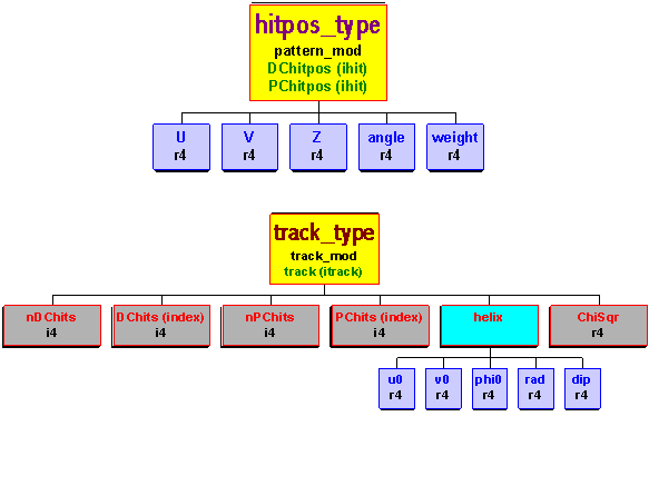
Figure 9 shows the proposed data structures for the hit position, hitpos_type, and the tracking, track_type. The components u, v, and z of the hit position structure will be initialized to wire positions. Once the timing information is translated to distance (and the tracking is done to resolve left-right ambiguity, etc) these components will contain the actual hit position. The component angle will contain the track intersection angle in the hit cell (which is needed by GARFIELD to convert the TDC time to distance), and the component weight will contain the weight for that hit to be used by the track fitting algorithm.
The track_type structure will contain the number
of hits in the DC and PC, nDChits
and nPChits as well
as the hit number as it appears in the TDC hit list in the tdc_type
structure (see the section Analysis Branch for details and examples).
The substructure helix
will contain the five helix parameters, and ChiSqr
the c2 value for the
track fit.

Figure 9. Proposed structures
for the hit position and tracking.